

Contents
What Is a Flywheel?
A flywheel is a heavy, rotating mechanical mass engineered to store kinetic energy as a function of its moment of inertia and angular velocity. It functions as a kinetic energy reservoir — absorbing surplus torque during power surges and releasing it during deficits to hold shaft speed close to constant.
The behavior traces back to conservation of angular momentum: absent external torque, a spinning mass holds its rotational state indefinitely, which is precisely the resistance-to-speed-change that makes a flywheel useful in the first place. The actual energy accounting, though, runs through rotational kinetic energy and moment of inertia — covered in full below.
The Working Principle of a Flywheel
Energy storage in a flywheel isn’t a function of mass alone — radius and rotational speed both carry far more mathematical weight, a fact most introductory explanations gloss over entirely.
Torque, Angular Acceleration, and Power Transfer
That smoothing traces back to one relationship: $T = I\alpha$ — net torque acting on the rotor produces angular acceleration. A torque surplus during the power stroke accelerates the flywheel; a deficit during compression or exhaust decelerates it, nothing more exotic than Newton’s second law in rotational form.
Energy moves in or out of the spinning mass through $P = T\omega$: mechanical power equals torque acting at the shaft’s angular velocity. Power flows in whenever torque exceeds what the load demands, and flows back out whenever the flywheel makes up the difference.
Rotational Kinetic Energy
The stored energy of a spinning flywheel follows directly from rotational mechanics:
$$E_k = \frac{1}{2} I \omega^2$$
- $E_k$ — kinetic energy stored, joules ($\text{J}$)
- $I$ — mass moment of inertia about the axis of rotation, $\text{kg} \cdot \text{m}^2$
- $\omega$ — angular velocity, radians per second ($\text{rad/s}$)
$I$ isn’t a fixed material property — it’s geometry-dependent:
$$I = k \cdot m \cdot r^2$$
- $k$ — inertial coefficient (dimensionless, shape-dependent)
- $m$ — rotating mass, $\text{kg}$
- $r$ — outer radius, $\text{m}$
$k$ swings hard depending on where the mass sits. A solid disk carries $k = 0.5$. A thin rim or hoop, where mass concentrates at the outer edge, approaches $k = 1.0$. That difference alone can nearly double stored energy for identical mass and radius — exactly why rim-loaded designs dominate serious flywheel engineering.
Weighing Mass, Radius, and Speed
Combine the two relationships above and stored energy becomes:
$$E_k = \frac{1}{2} k m r^2 \omega^2$$
Read the exponents directly: mass enters linearly, while radius and angular velocity both enter squared — equal mathematical weight, not a hierarchy.
Doubling mass ($m’ = 2m$) doubles $E_k$ — straightforward proportionality. Doubling radius ($r’ = 2r$), with $m$ and $\omega$ held fixed:
$$E_2 = \frac{1}{2} k m (2r)^2 \omega^2 = 4E_1$$
Doubling angular velocity ($\omega’ = 2\omega$), with $m$ and $r$ held fixed, follows the identical pattern:
$$E_2 = \frac{1}{2} k m r^2 (2\omega)^2 = 4E_1$$
Both doublings quadruple stored energy — radius and speed carry equal mathematical weight, contrary to how some flywheel write-ups frame it. Mass is the only linear term, which is why high-speed composite rotors beat heavy steel ones on a mass basis: identical energy from a fraction of the material, provided the rotor survives the stress. Radius, by contrast, can’t grow without adding material and footprint — exactly why compact, high-speed flywheel designs chase speed over bigger rotors.
And speed can’t climb forever. Tangential stress in a thin rotating rim scales as:
$$\sigma \approx \rho (\omega r)^2$$
where $\rho$ is material density and $\omega r$ is tip speed. Push $\omega$ high enough and hoop stress eventually exceeds the material’s tensile limit — the reason composite rotors, with their favorable strength-to-density ratio, unlock speeds steel rotors can’t touch without bursting.
Worked Example: Sizing a Solid Disk Flywheel
Take a uniform solid disk — $k = 0.5$ — with mass $m = 50\ \text{kg}$, radius $r = 0.30\ \text{m}$, spinning at $N = 1{,}500\ \text{RPM}$.
Moment of inertia:
$$I = \frac{1}{2} m r^2 = \frac{1}{2}(50)(0.30)^2 = 2.25\ \text{kg} \cdot \text{m}^2$$
Angular velocity:
$$\omega = \frac{2\pi N}{60} = \frac{2\pi (1{,}500)}{60} \approx 157.1\ \text{rad/s}$$
Stored kinetic energy:
$$E_k = \frac{1}{2} I \omega^2 = \frac{1}{2}(2.25)(157.1)^2 \approx 27{,}758\ \text{J} \approx 27.8\ \text{kJ}$$
Double the rotational speed to $3{,}000\ \text{RPM}$ and $\omega$ doubles too — per the quadratic relationship above, stored energy quadruples to roughly $111\ \text{kJ}$, without changing the rotor’s mass or radius at all.
Coefficient of Fluctuation of Speed
Every reciprocating or intermittent-load system produces speed ripple across each cycle — the flywheel’s entire job is bounding that ripple. Engineers quantify it with the coefficient of fluctuation of speed, $C_s$:
$$C_s = \frac{\omega_1 – \omega_2}{\omega_0}$$
- $\omega_1$ — maximum angular velocity in the cycle
- $\omega_2$ — minimum angular velocity in the cycle
- $\omega_0$ — mean angular velocity, $\omega_0 = \frac{\omega_1 + \omega_2}{2}$
Swap in rotational speed $N$ (RPM) instead of $\omega$ — the $\frac{2\pi}{60}$ conversion factor cancels cleanly out of the ratio:
$$C_s = \frac{2(N_1 – N_2)}{N_1 + N_2}$$
This isn’t just descriptive — it’s a direct sizing tool. Combine $C_s$ with the energy equation and the algebra collapses nicely:
$$\Delta E = E_1 – E_2 = \frac{1}{2}I(\omega_1^2 – \omega_2^2) = I\omega_0(\omega_1 – \omega_2) = I\omega_0^2 C_s$$
Rearranged for design use:
$$I = \frac{\Delta E}{C_s \cdot \omega_0^2}$$
Feed in the known energy fluctuation per cycle ($\Delta E$, from the load profile) and a target $C_s$ — punch presses tolerate roughly $0.10$ to $0.20$; precision generator sets demand closer to $0.003$ to $0.01$ — and the required moment of inertia falls straight out. This single equation is most of what “sizing a flywheel” actually means in practice.
Flywheel vs. Governor
The two get confused constantly, but they regulate different things on different timescales.
| Flywheel | Governor | |
| Controls | Cyclic speed fluctuation within a single cycle | Average speed across many cycles |
| Mechanism | Passive — stores and releases kinetic energy | Active — throttles fuel, steam, or air input |
| Response | Milliseconds, mechanical | Seconds, feedback-driven |
A flywheel smooths the ripple; it can’t fix a sustained speed drift — once its stored energy is spent, it settles at whatever average the load allows. That’s the governor‘s job: watching average speed and adjusting energy input to hold it near a setpoint, alongside the flywheel rather than in place of it.
Key Components of Flywheel Systems
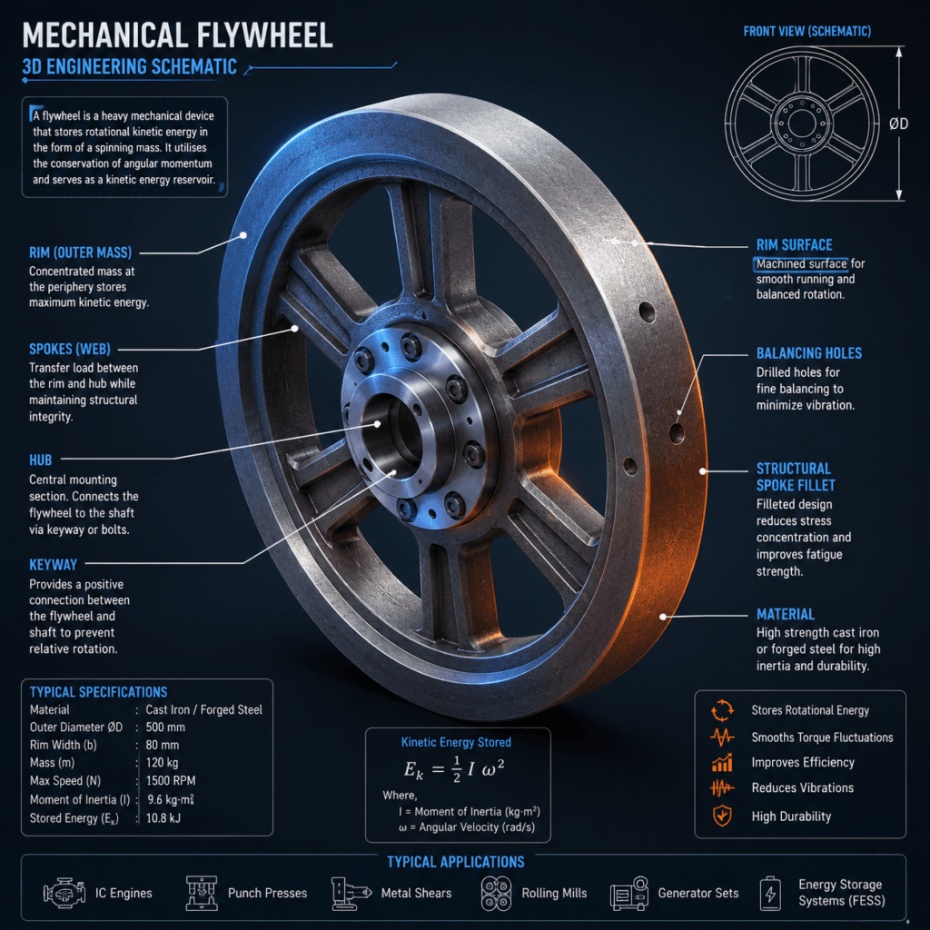
Strip a flywheel to its structural skeleton and three zones do all the work, each under a different stress regime.
Rim
The rim is the outer band where designers deliberately concentrate mass. Since $I \propto r^2$, pushing mass to the largest practical radius returns the most inertia per kilogram — the rim exists entirely because of that squared relationship.
Rim cross-sections run thick relative to the web, and material selection tracks directly to operating speed: cast iron and forged steel dominate conventional designs, composite laminates take over once tip speed pushes past what steel’s tensile strength allows.
Web / Spokes
Load moves from rim to hub through the web — or spokes, in lighter designs — carrying two distinct stress types at once: radial tension from the rim’s centrifugal pull outward, and torsional shear from the torque passing through.
Solid webs suit high-speed, high-stress applications where a continuous disk resists deformation better than discrete spokes. Spoked designs shed unnecessary mass in large, slow industrial flywheels where minimizing total weight matters more than peak stress tolerance.
Hub
Bore, keyway or spline, mounted directly on the drive shaft — that combination is the hub, the sole interface transmitting torque into and out of the rotating assembly. Fit tolerance here determines how much backlash or vibration reaches the flywheel under load reversal.
Modern Flywheel Energy Storage Systems (FESS)
Classical rim-web-hub geometry still applies inside a Flywheel Energy Storage System, but four additional subsystems turn a mechanical buffer into a grid-grade “mechanical battery.”
High-Tensile Rotor Mass
FESS rotors are typically wound carbon-fiber composite, not cast metal. Composite’s strength-to-density ratio dwarfs steel’s — the reason it permits tip speeds steel would shear apart at. That’s the direct engineering payoff of the $\sigma \approx \rho(\omega r)^2$ relationship covered above.
Magnetic Levitation Bearings
Active magnetic bearings suspend the rotor with zero mechanical contact, cutting friction losses dramatically — but not to zero. Eddy-current losses, magnetic hysteresis, control-system power draw, motor-generator conversion losses, residual windage, and auxiliary power consumption for the levitation electronics all persist. Some designs pair magnetic bearings with mechanical touchdown bearings reserved strictly for power-loss failsafe events, not routine operation.
Vacuum Enclosure
At tens of thousands of RPM, aerodynamic drag — windage loss — would dominate the energy budget even with frictionless bearings. Sealing the rotor inside an evacuated housing greatly reduces windage losses, which is why FESS units are hermetic by design rather than open to atmosphere.
Integrated Motor/Generator
A permanent-magnet or reluctance machine built directly onto the rotor shaft handles both directions: motoring to spin the rotor up during charging, and generating to extract stored energy on demand during discharge, switched electronically through a bidirectional inverter.
Major Types of Flywheels
Solid Disk Flywheels
Mass distributes continuously from hub to rim rather than concentrating at the edge, giving a comparatively low inertial coefficient — $k \approx 0.5$ for a uniform disk. Cast iron and steel dominate the category, machined post-casting for balance.
Manufacturing simplicity is the entire appeal here. Solid disks show up in cost-sensitive automotive and small-engine applications where peak energy density isn’t the design driver.
Rimmed Flywheels
Push mass out to a thickened rim instead, connected to the hub through a thin web or spoke pattern, and $k$ climbs toward $1.0$ — extracting substantially more inertia per kilogram than a solid disk.
The trade-off is structural: concentrating mass at large radius raises hoop stress at any given speed, per the $\sigma \approx \rho(\omega r)^2$ relationship. That caps the safe burst-speed threshold below what an equivalent-mass solid disk could theoretically tolerate. Engines, presses, and general industrial machinery use this geometry almost universally.
High-Velocity Flywheels
Operating range: roughly $30{,}000\text{ RPM}$ to $100{,}000\text{ RPM}$. Conventional contact bearings become increasingly impractical at these speeds because of friction, wear, lubrication, and thermal limitations.At that speed, so the category is inseparable from magnetic suspension, composite rotors, and vacuum housings.
Specific energy (energy per unit mass) climbs steeply here — a direct payoff of the $E_k \propto \omega^2$ relationship. Deployment sits in grid-scale FESS, motorsport kinetic energy recovery systems (KERS), and uninterruptible power supply (UPS) backup.
Low-Velocity Flywheels
Traditional cast-iron and steel construction, generally capped near $10{,}000\text{ RPM}$ — and in large industrial installations, often running a small fraction of that given size and stress constraints. These designs lean on raw mass rather than rotational speed for their energy budget.
Heavy low-speed flywheels frequently demand substantial foundation mass — concrete plinths in stationary industrial settings — to absorb vibration and whatever gyroscopic reaction load the mounting geometry produces, which tracks angular momentum ($I\omega$) rather than mass or speed in isolation.
Where Flywheels are Deployed
Internal Combustion Engines
A four-stroke cycle produces net positive torque during exactly one stroke — power. Compression, exhaust, and intake contribute nothing, or actively consume torque. Left unaddressed, that’s a brutally discontinuous torque curve.
The flywheel absorbs the power stroke’s surplus and bleeds it back out through the other three, smoothing raw torque pulses into something close to constant crankshaft speed. Single-cylinder engines need proportionally larger flywheels than multi-cylinder designs — a V8’s overlapping power strokes already do much of the smoothing mechanically, before the flywheel contributes anything.
Punch Presses & Metalworking Shears
The drive motor spins the flywheel continuously through the idle, or dwell, portion of the cycle — building stored energy gradually and cheaply. At the instant of the punching or shearing stroke, that stored energy discharges almost instantaneously through a clutch, delivering peak power the drive motor alone could never supply continuously.
That’s the real economic argument: manufacturers spec a motor sized for average load, not peak load, and let the flywheel absorb the difference. Undersizing the flywheel here doesn’t just hurt performance — it forces a disproportionately larger, more expensive motor to compensate.
Grid Stabilization Systems
Modern FESS installations function as millisecond-response mechanical batteries for grid frequency regulation — absorbing or discharging power fast enough to counteract frequency deviations before they propagate. Beacon Power’s Stephentown, New York plant is the reference case: $200$ flywheels rated at roughly $0.1\text{ MW}$ each, aggregating to $20\text{ MW}$ and about $5\text{ MWh}$ of fast-response capacity, selling regulation service directly into the NYISO market.
The application has only grown more relevant, not less, as synchronous generation — coal, gas, nuclear plants whose massive rotating turbines supply natural grid inertia — gets displaced by inverter-based solar and wind. Solar contributes essentially zero rotational inertia of its own, and grid operators need fast-acting substitutes.
Utility-scale flywheel frequency-regulation deployments now extend well beyond the original U.S. pilot projects, including large installations reported across multiple provinces in China. This is a mature ancillary-services technology, not an experimental one.
Flywheel Energy Storage vs. Chemical Batteries
| Parameter | Flywheel (FESS) | Lithium-Ion Battery |
| Storage Mechanism | Kinetic — rotational mass | Electrochemical — ion intercalation |
| Cycle Life | $>10^5$ cycles typical — mechanical wear-limited, not chemistry-limited | Typically $1{,}000$ to $5{,}000$ cycles, chemistry- and depth-of-discharge-dependent |
| Response Time | Milliseconds — near-instantaneous | Fast, but governed by electrochemical reaction kinetics |
| Environmental Impact | Steel/composite/copper, largely recyclable, no toxic electrolyte | Lithium, cobalt, nickel mining footprint; e-waste and recycling complexity |
| Thermal Runaway / Safety Risk | None chemically; primary risk is mechanical rotor burst | Documented thermal runaway risk, requires active battery management |
| Round-Trip Efficiency | $85%$ to $95%$, magnetic-bearing systems trending toward the top of that band | $85%$ to $95%$, broadly comparable across modern chemistries |
Cycle life is where the technologies diverge hardest. A flywheel discharging to full depth every cycle has no electrochemical capacity to fade in the first place — but bearings, seals, vacuum equipment, sensors, and power electronics still wear, so real service life is set by those components, not by a cycle count. A lithium-ion cell, by contrast, accumulates chemical degradation with every cycle, calendar-aged or not.
Round-trip efficiency, by contrast, isn’t the knockout argument some flywheel marketing implies — modern Li-ion systems land in roughly the same band. The actual differentiator sits in duty cycle: flywheels win on power-dense, high-frequency, short-duration cycling; batteries win on energy-dense, long-duration storage.
Symptoms of a Damaged Automotive Flywheel
- Slipping under acceleration — engine RPM climbs without a proportional increase in road speed, often traced to a glazed or heat-scored flywheel friction surface rather than the clutch disc alone
- Clutch chatter / pedal pulsation — a warped flywheel face, or localized hot spots from repeated slip, causes uneven engagement transmitted straight through the pedal and drivetrain
- Localized burning smell — friction material overheating against a flywheel surface that’s lost its even contact plane
- Starter motor grinding — sheared or worn teeth on the flywheel’s ring gear, preventing the starter pinion from engaging cleanly
- Sudden stalling profiles, particularly at low RPM or idle, from inconsistent torque transfer through a damaged engagement surface
Dual-mass flywheels (DMF) fail differently than solid single-mass units. A worn internal arc-spring damper produces a distinct rattling or knocking noise at idle in neutral that disappears once the clutch is depressed — a symptom most single-mass flywheel diagnostics skip entirely, and one that’s easy to misdiagnose as a loose exhaust heat shield or timing chain slap.
None of these symptoms points to the flywheel exclusively — worn clutch discs, weak pressure plates, failing engine mounts, and loose exhaust hardware produce overlapping symptoms, so proper inspection before replacement is essential.
Engineering Advantages and Critical Limitations
Advantages
- No electrochemical degradation — full-depth cycling doesn’t fade capacity the way battery chemistry does, though bearings, seals, and composite rotor interfaces still have finite service lives
- Wide operating temperature range — performance doesn’t collapse in extreme heat or cold the way electrochemical storage does
- No thermal runaway or fire hazard from the storage mechanism itself
- High power density and near-instantaneous response, ideal for short, sharp discharge demands
Critical Limitations
- High self-discharge / parasitic losses — even magnetic-bearing, vacuum-housed rotors bleed a measurable percentage of stored energy per hour through residual bearing drag and minimal windage, ruling FESS out for long-duration, multi-hour-plus storage
- Catastrophic kinetic failure risk — exceed the rotor material’s hoop-stress limit (over-speed, material flaw, bearing failure causing rotor-housing contact) and the rotor can fail violently, releasing its full stored energy at once; containment engineering isn’t optional, it’s structural
- Gyroscopic torque — a spinning rotor’s angular momentum resists reorientation of its spin axis, following $\tau_g = I\omega\Omega\sin\theta$: reaction torque scales with moment of inertia, spin speed, imposed precession rate, and the angle between the two axes, not with mass or speed in isolation. Mobile platforms — vehicles, vessels, aircraft — experience this on every pitch, roll, or yaw maneuver, a constraint stationary grid installations never have to engineer around